Photo Examples of Mobile Home Compliance Issues
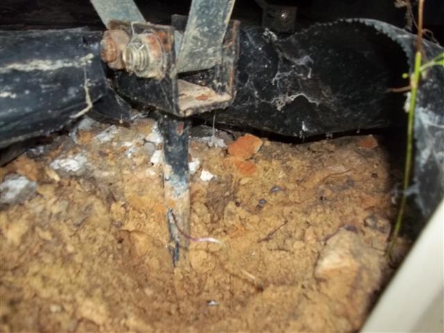
(1) Our inspector took this inspection photo of a non-compliant anchor… notice that there is no concrete around the anchor stem or head.
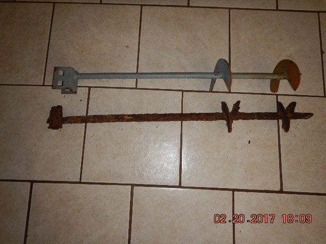
(1a) This is an inspection photo of anchor stems used to anchor the home to the ground…. both anchors are 31 inches in length. The bottom anchor had been in ground less than 4 years with no concrete collar and already was severely corroded. The top anchor is what the bottom anchor originally would have looked like.
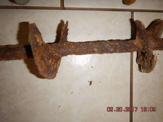
(1b) Close-up inspection photo of the anchor that had been in ground less than 4 years with no concrete collar and already severely corroded.
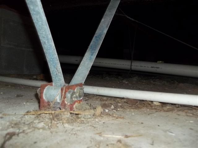
(2) Our inspector took this inspection photo of an FHA/HUD compliant anchor… notice that the anchor stem and head is set in concrete.
(3) Our inspector took this photo of a corrosion-resistant galvanized anchor that started to be used in 2012/2013 by some installers. It is corrosion resistant and thus meets FHA/VA/USDA/HUD as well as Texas TDHCA Guidelines.
(3a) This inspection photo shows what happens when the spacing of the anchors is too great and there is not enough wind resistance. Over a period of time, the anchor and its concrete collar have been pulled out of the ground and neutralized as a structural element of the foundation
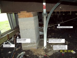
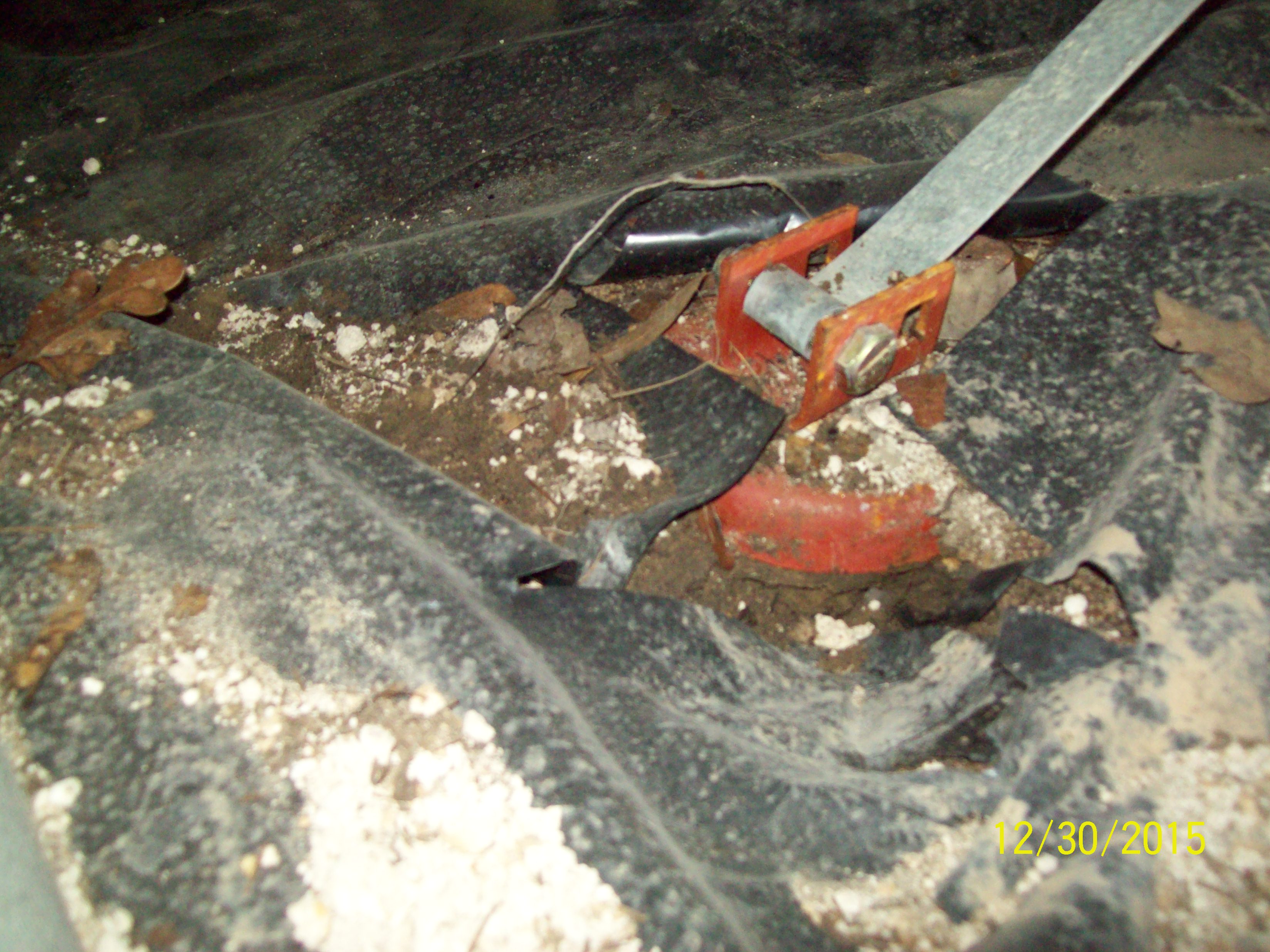
(3b) Our inspector took this inspection photo that shows several issues addressed in the FHA/VA/HUD 1996 Guidelines for Manufactured Home Foundations
- The transverse anchor is set in concrete but the straps are vertical… the straps should have been run to the interior frame
- The longitudinal anchor is set in soil… it should have been set in the concrete footing on which the transverse anchor is set
- The concrete footing appears to be in satisfactory condition
- The skirting bracing is also set properly.
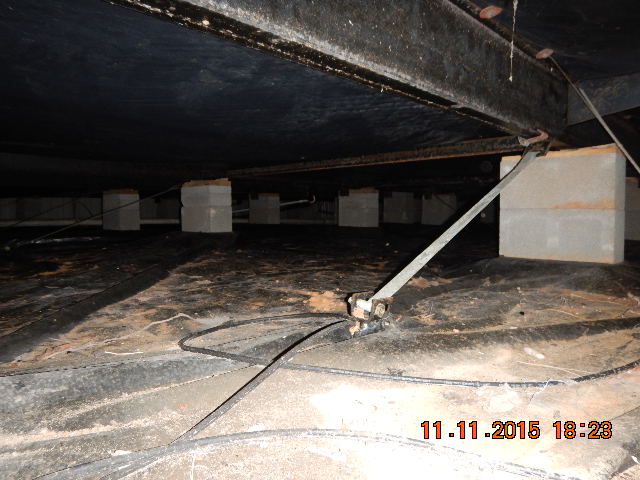
(4) Properly installed longitudinal anchor. The anchor stem is embedded in concrete (the same longitudinal concrete runner on which the cinderblock pier is set ), the strap is at a reasonable angle and secured to the frame properly.
(5) In this inspection photo, the anchor stem is embedded in the same concrete footing onto which the cinderblock pier is set. One strap goes almost vertical to the exterior frame and the other strap extends to the interior frame at an angle ranging from 30 to 45 degrees from horizontal. This anchor arrangement meets FHA/VA/USDA/HUD as well as Texas TDHCA guidelines

(6) Another recent example of both a transverse and a longitudinal anchor properly installed. Notice that both anchor stems are set in the concrete longitudinal runner. Note also that the transverse anchor has the strap running at an angle to the interior frame and not vertical to the exterior frame.
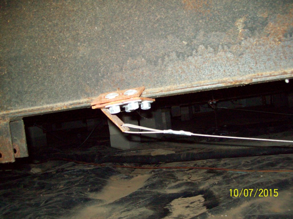
(7) Our inspector took this inspection photo as an sample close-up of how a longitudinal anchor strap is attached to the frame of the home.
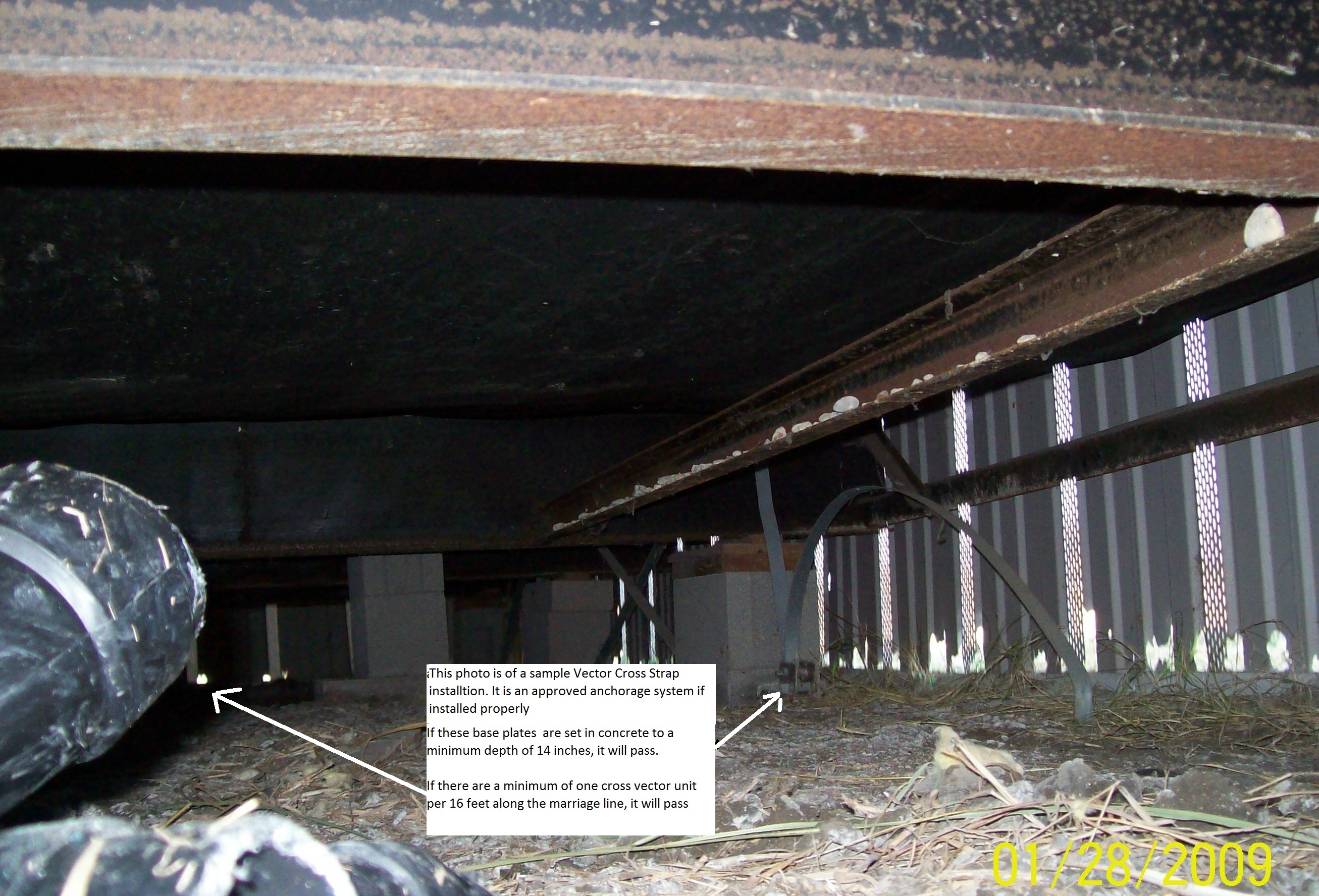
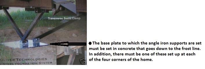
(7a) Sample Cross Vector Strap anchorage system. Our inspector took this inspection photo showing a sample Vector Cross Strap installation. It is an approved anchorage system if installed properly. If the base plates are set in concrete to a minimum depth of 14 inches, it will pass. If there are a minimum of one cross vector unit per 16 feet along the marriage line, it will pass.
(7b) Our inspector took the above inspection photo of a anchoring system that does meet FHA/VA/HUD and Texas TDHCA guidelines if installed properly.
(7c) The above type anchor system must also be set
1. at all four corners for a doublewide and
2. at each end for a singlewide
It would also be preferable if the mild steel shown in this photo were coated with a corrosion resistant paint to inhibit rust and extend the life of the system.
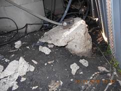
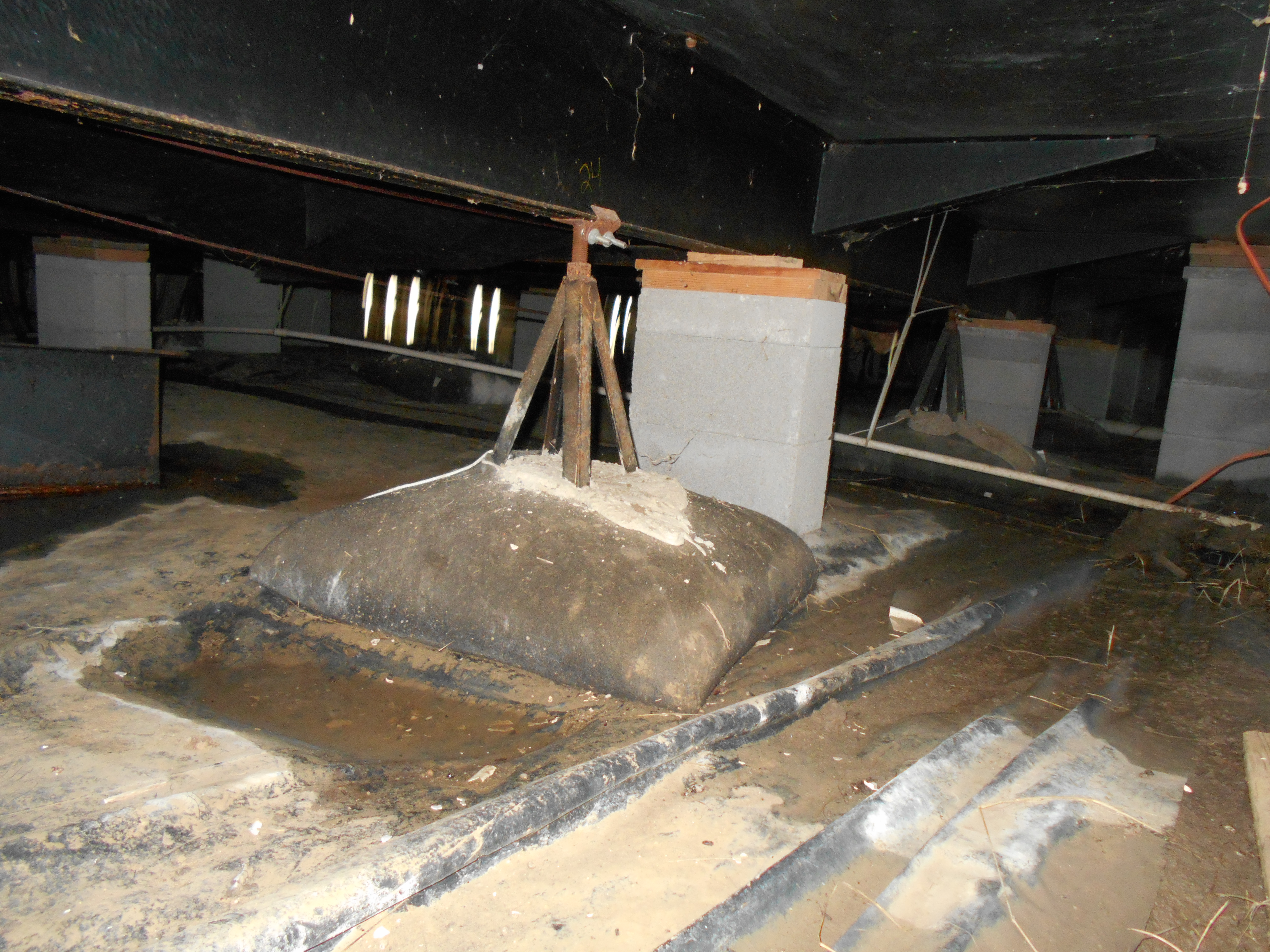
(8) This type foundation is variously called a Magnum or Bigfoot Manufactured Home Foundation Pier. If the base plate is secured to a concrete footing that goes down at least 12 inches into the ground, it will pass. However, there are many cases, such as the one in the photo above, where the base is simply setting on the ground and does not pass. In addition, this pier must be set at all four corners of the home, at a minimum, in order to pass.
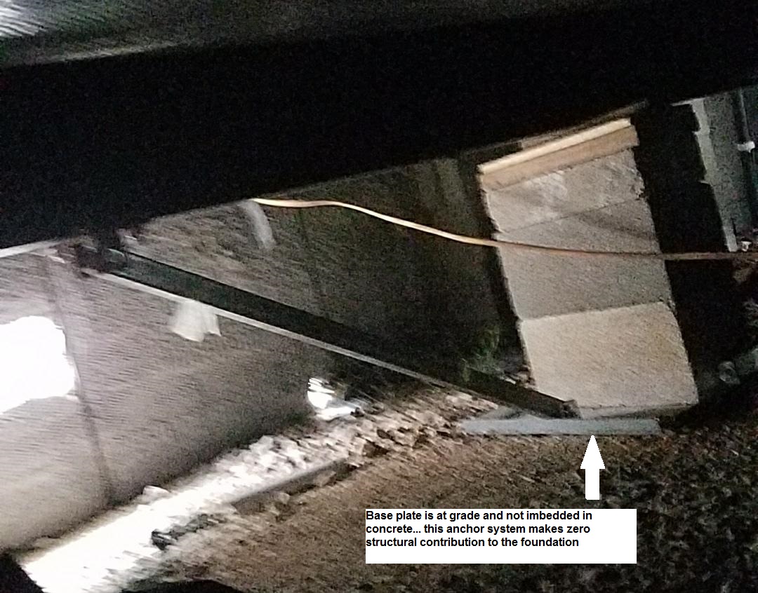
(8a) Non-compliant anchor system.
The anchor system in this inspection photo would be compliant if the pad were set in concrete that was at least 12 inches deep. Instead, the pad is simply sitting on the ground at grade and contributes effectively zero wind resistance for the home
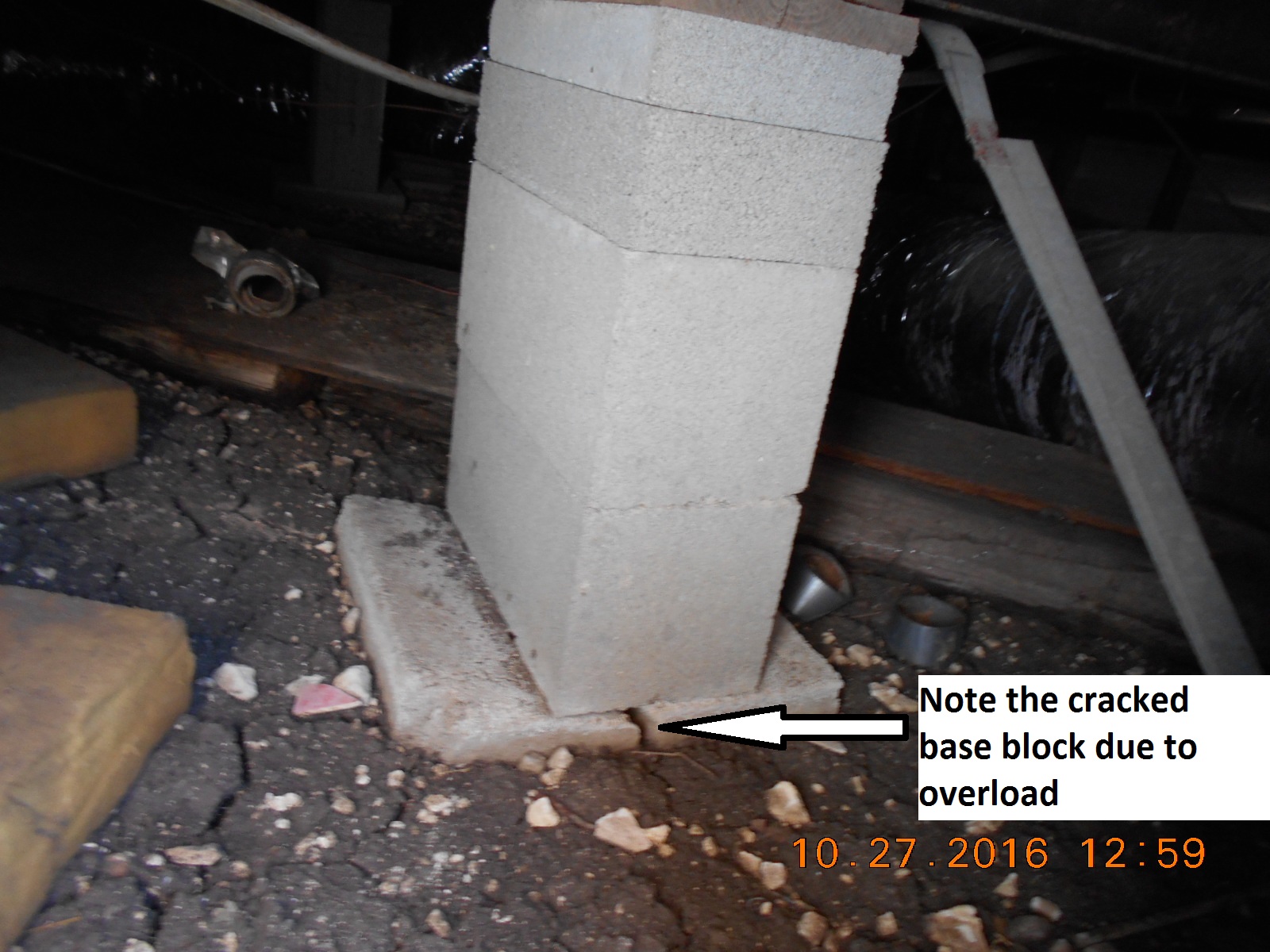
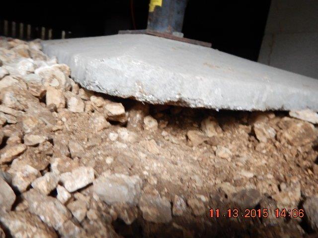
(8b) This inspection photo shows what can happen when a single pier is overloaded and near failure. The height of this pier should have required double stacked cinder blocks and also a concrete footing under the pier to provide stability.
(8c) Another example of an improperly installed BigFoot or equivalent system…. If the base plate had been embedded in a concrete footer extending a minimum of 8 inches below grade (preferable 12 inches ), it would have passed.

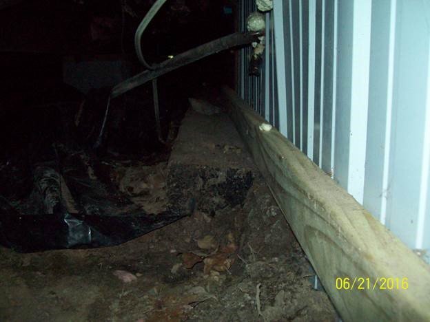
(9) The inspection photo above is of skirting with substantial weed-eater damage as well as missing the required bracing…. notice the runners at the bottom laying on the ground versus on treated lumber.
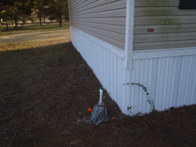
(10) The inspection photo above is of undamaged skirting.
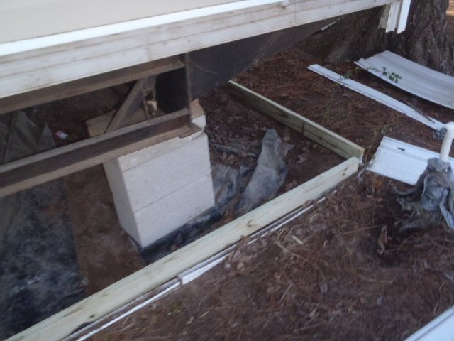
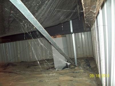
(11) This inspection photo from inside the crawlspace shows the corner bracing using treated 2 X 4’s for the bottom of the vinyl skirting. As long as the 2 X 4 is secured, at each end, to the ground by rebar or other material to prevent lateral movement, it will meet code.
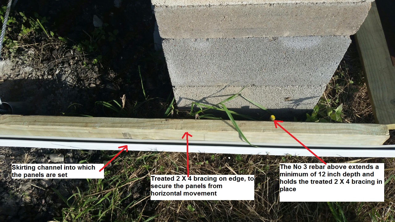
(11a) The above inspection photo is a close-up of bracing being installed prior to the panels being placed. Note the rebar already set in place. This type bracing will hold skirting that is up to 36 inches in height…. Skirting higher than that may need an additional horizontal brace midway between the bottom brace and the top trim.

(12) For skirting higher than 30 inches, there also needs to be vertical bracing placed every 8 to 10 feet.
 !
!
(12a) This recent inspection photo shows a close-up of the treated 2 X 4 needed to supply wind bracing for vinyl skirting.
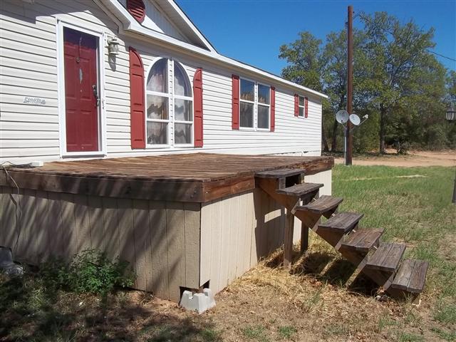
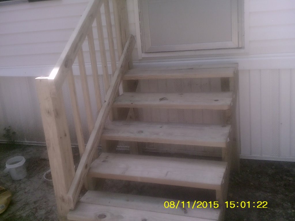
(13) The inspection photo above is of decking and steps in excess of 30 inches in height that do not have the required hand rails and balusters.
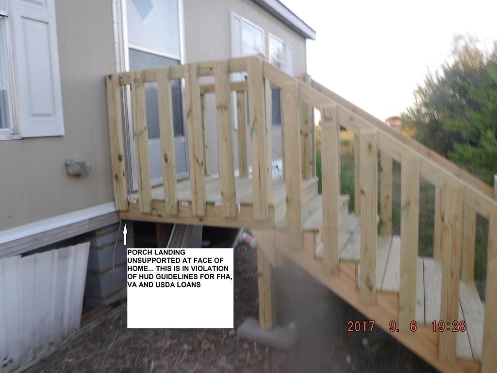
(13a) The above porch/steps were installed properly, with the one exception that the landing does not have a 4X4 support post at the face of the MH. Thus the landing ( a modification by HUD definition ) transfers a load to the home and thereby violates HUD Guidelines for FHA, VA and USDA Loans. The 4X4 posts at the opposite end of the landing are properly installed.
(14) Specifications for porch/landing/steps handrails and balusters.
For any porch/landing/steps 30 inches or higher,
- Treated wood for both handrails and balusters.
- Handrails height should be 30 inches.
- Balusters should be installed vertically, 32 inches long and 6 inches center to center.
- Steps need handrail and balusters on one side only.
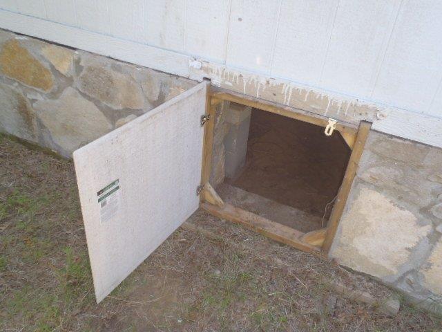
(15) This is an example of properly installed skirting manway. 1 of 3
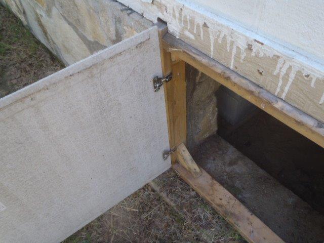
(16) This is an example of properly installed skirting manway. 2 of 3
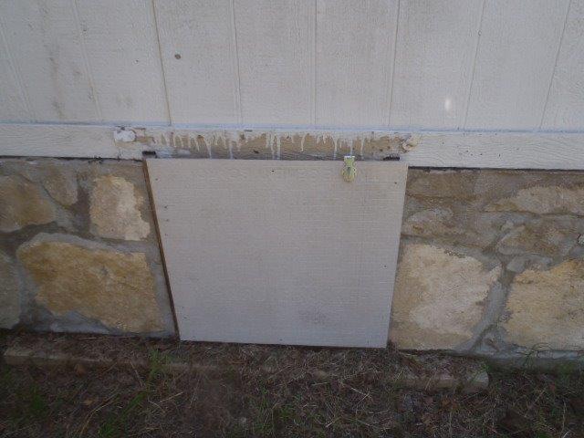
(17) This is an example of properly installed skirting manway. 3 of 3
(18) This type of stairs is non-compliant…. The top step must be near level with the floor of the house… there cannot be a significant drop from the floor to the first step.
(19) This is an example of properly built steps.
(20) The above porch roof has support posts on the outside but none at the face of the home…. four(4) posts need to be set at the face of the home to take all of the porch roof load away from the home itself.
(20a)
This is a properly installed treated 4”X 4” porch roof support post supporting the left corner of this porch roof… a similar post was on the right roof corner

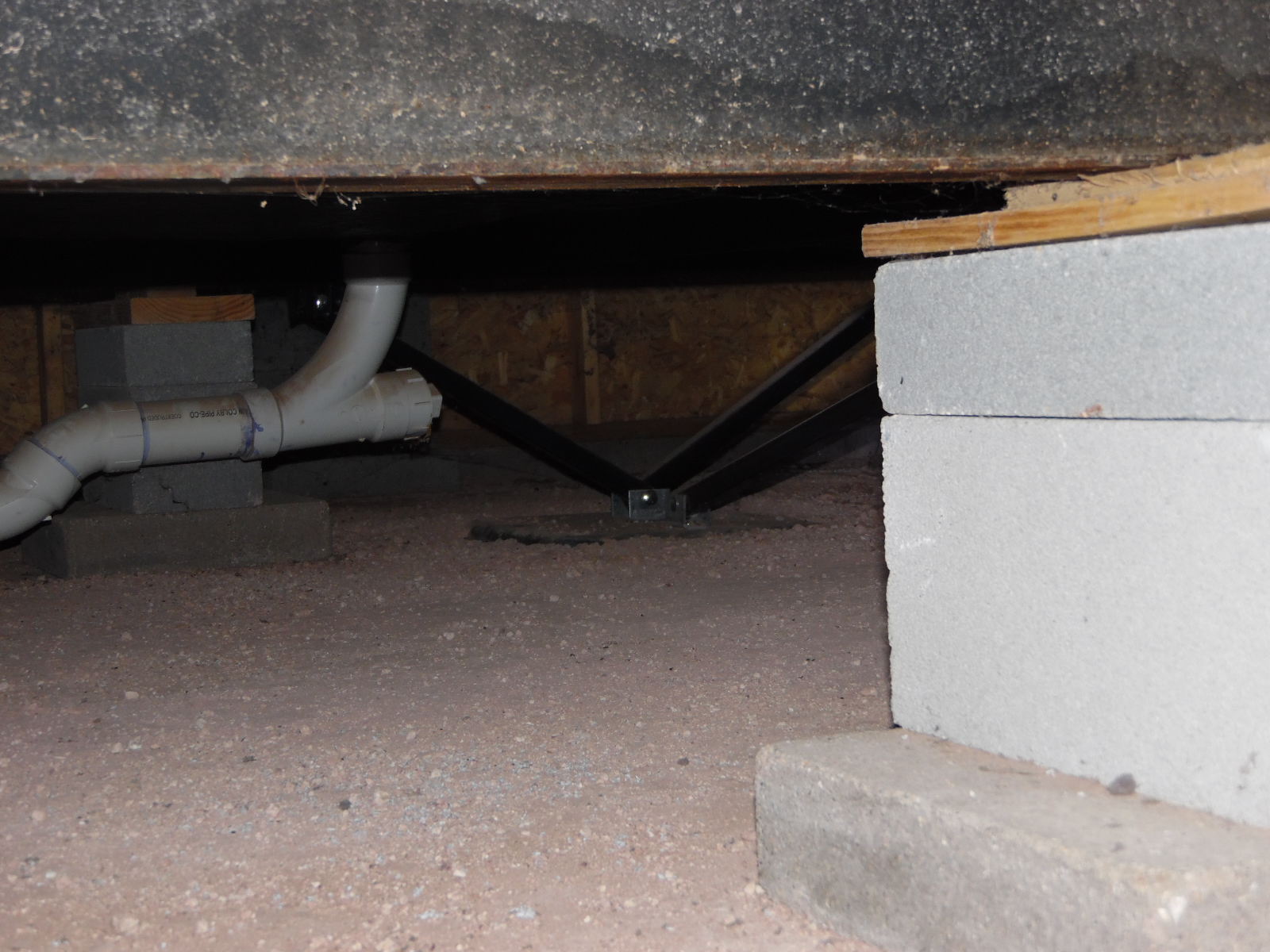
(21) The above inspection photo from a recent inspection shows a properly installed transverse concrete runner and a cinderblock pier mounted on it.
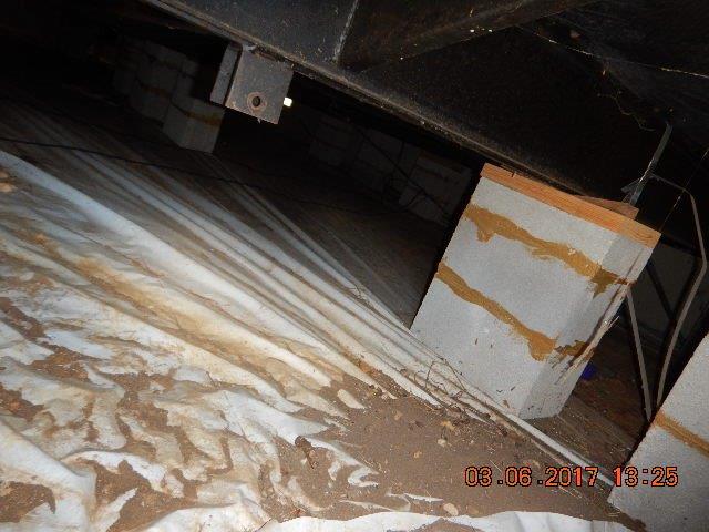
(22) Some lenders are requiring that the dry stack cinderblock piers have some sort of epoxy binding agent as is shown in the above photo. We disagree with this finding…. it provides no contribution to the structural purpose of the cinderblock pier.